SoOrthoSlice Class Reference
[Nodes]
 Ortho slice shape node.
More...
Ortho slice shape node.
More...
#include <VolumeViz/nodes/SoOrthoSlice.h>
Public Types | |
| enum | Axis { X, Y, Z } |
| enum | ClippingSide { FRONT, BACK } |
Public Member Functions | |
| virtual SoType | getTypeId () const |
| SoOrthoSlice () | |
| virtual bool | intersect (SoLDMNodeFrontManager *nfm, const SoLDMTileID &tileId) |
Static Public Member Functions | |
| static SoType | getClassTypeId () |
Public Attributes | |
| SoSFUInt32 | sliceNumber |
| SoSFEnum | axis |
| SoSFEnum | clippingSide |
| SoSFBool | clipping |
Detailed Description
Ortho slice shape node.
This node defines an ortho (axis aligned) slice along the X, Y, or Z axis of the volume data defined by an SoVolumeData node. The slice orientation and position are defined by the axis and sliceNumber fields.
For a non-RGBA (scalar valued) volume, each voxel's RGBA value is determined by the current SoDataRange and SoTransferFunction. The current diffuse color and transparency (set, for example, with an SoMaterial node) modifies the appearance of the slice. This means that, for example, the current transparency can be used as a global alpha value to modulate the overall opacity of the slice. For an RGBA volume each voxel's RGBA value comes directly from the volume data.
The interpolation field controls how the texture is interpolated.
The alphaUse field (SoSlice) controls how the voxel's alpha component is used when drawing the slice.
Optionally a bump mapping effect may be applied. Normal vectors are automatically computed from the data value gradient. The enableBumpMapping and bumpScale fields (SoSlice) control whether bump mapping is active and the intensity of the effect.
Notes:
- Drawing position:
The SoOrthoSlice geometry passes through the center of the voxels in the specified slice. So, for example, an ortho slice with sliceNumber = 0 will be drawn one-half voxel size (on the slice axis) in from the bounding box of the volume. This is slightly different than SoVolumeSkin. A volume skin is approximately the same as six ortho slices, but each face of the skin is drawn at the outer edge of the voxel.
- Transformation matrices:
The volume size and orientation (like geometry) can be modified by transformation nodes in the scene graph and this in turn modifies the appearance of volume visualization nodes. However the same transformation must be applied to the volume data node and all volume visualization nodes associated with that volume. So effectively any transformation nodes that affect the volume must be placed before the volume data node.
- Picking:
The entire slice is pickable, even where it is transparent as a result of the current transfer function. The SoOrthoSliceDetail class allows you to get the voxel position and value after picking.
- Dragging:
It is possible to interactively translate and rotate slices using an Open Inventor dragger, e.g. SoTranslate1Dragger. However the dragger's position in XYZ space must be converted to a slice number. For a dragger that is specific to ortho slices, see the class SoOrthoSliceDragger.
- Interpolation:
Interpolation is specified using the interpolation field. The default (LINEAR) does bi-linear interpolation between voxel values. The NEAREST value can be used to display individual voxels. For best image quality we recommend using the MULTISAMPLE_12 value.
- Data range:
By default VolumeViz maps the entire range of the voxel's data type (e.g. 0..65535 for unsigned short) into the colormap. This is often correct for byte (8 bit) voxels, but seldom correct for 16 bit voxels and never correct for floating point voxels. Use an SoDataRange node to specify the actual (or desired) range of data values to be mapped. Also use an SoDataRange node to implement brightness/contrast control like the Window/Level setting commonly used with medical images.
- Clipping:
Volume primitives can be clipped using a region of interest (SoROI), geometry (SoVolumeClippingGroup) and/or height fields (SoUniformGridClipping). They are also clipped by OpenGL clipping planes (SoClipPlane), but we recommend using the VolumeViz clipping nodes instead.
Optionally, this node also defines a clipping plane. Similar to SoClipPlane, this clipping plane affects all subsequent geometry, including SoVolumeRender, but does not of course affect the ortho slice itself. The clipping and clippingSide fields control whether clipping is active and which half-space is clipped. Clipping side FRONT means that the clip plane (removes) clips away geometry in the positive direction on the slice axis.
- Material:
The color of each voxel is modulated by the current diffuse color in the traversal state. The default diffuse color is 0.8,0.8,0.8. This results in full intensity values in the color map being displayed as 80% intensity. Therefore we recommend adding an SoMaterial node before the slice and setting its diffuseColor field to full white (1,1,1).
- Transparency:
- Typically the color map (SoTransferFunction) used for volume rendering (SoVolumeRender) assigns transparency (alpha < 1) to some voxel values. If you want to use the same color map for slice rendering, but render the slice completely opaque, set the alphaUse field to ALPHA_OPAQUE. This overrides the alpha values in the color map (or an RGBA volume). However it does not affect transparency assigned using an SoMaterial node.
- If you want to adjust the overall transparency of the slice, add an SoMaterial node and set its transparency field (keeping alphaUse set to ALPHA_AS_IS). Effectively a scale factor 1-transparency is applied to each voxel's alpha value.
- Intersecting transparent slices cannot be rendered correctly by the basic blending transparency algorithms. To render this case correctly, set the transparency algorithm to SORTED_PIXELS_BLEND (or similar value) using the viewer class or SoGLRenderAction.
- Typically the color map (SoTransferFunction) used for volume rendering (SoVolumeRender) assigns transparency (alpha < 1) to some voxel values. If you want to use the same color map for slice rendering, but render the slice completely opaque, set the alphaUse field to ALPHA_OPAQUE. This overrides the alpha values in the color map (or an RGBA volume). However it does not affect transparency assigned using an SoMaterial node.
- Voxel edges:
The edges of the voxels can also be rendered. See options in the SoVolumeRenderingQuality node.
- Custom shaders:
The current SoVolumeShader node, if any, allows custom shaders to be defined for special computation or rendering effects, including blending multiple volumes.
- Large Slice mode:
When the "large slice" mode is enabled (see SoSlice::largeSliceSupport), if all the required full resolution tiles have already been loaded, then the slice data is taken from LDM system memory cache as usual. But if some required tiles are not currently in memory, the required slice data will be loaded directly from the volume reader without loading the complete tiles. This reduces disk I/O and reduces the amount of system memory required to display the slice at full resolution, so larger (or more) slices can be displayed. The required tiles are then scheduled to be loaded asynchronously in case adjacent slices are displayed later. For example, loading a 1024x1024 SoOrthoSlice from an 8-bit dataset with 128x128x128 tiles would normally require loading 1024x1024x128 bytes of data (as complete tiles). With largeSliceSupport enabled, only 1024x1024 bytes (maximum) of data need to be loaded (in the worst case where no high resolution data is currently in memory).
- Performance:
- Tile size:
For backward compatibility, the default tile size is still only 64. This is quite small for modern CPU/GPU hardware. The smaller the tile size, the larger the total number of tiles that must be managed by VolumeViz. This overhead can be significant, especially for operations that require reloading the data textures on the GPU, for example, changing the data range (SoDataRange). For smaller volumes, like 512^3, it can be efficient to set the tile size large enough to contain the entire volume. For very large volumes, larger tile sizes are efficient for SoVolumeRender but somewhat inefficient for slice rendering because complete tiles must be loaded even though the slice only uses part of the data. Applications should experiment.
For volumes stored in LDM file format, the tile size must be specified when the volume is converted to LDM (see SoConverter and the "-t" option). For other data data formats the tile size can be specified using the SoVolumeData node's ldmResourceParameters field, but only after setting the filename field or calling the setReader() method.
- LDM_USE_IN_MEM_COMPRESSION
VolumeViz always manages data as "tiles", regardless of the data format. In many cases VolumeViz must create (or uncompress) the tiles at run time. These cases include in-memory volumes, any volume reader that does not implement the readTile() method (this includes all built-in formats except LDM, e.g. DICOM, SEGY, ...) and compressed LDM format files. If this variable is true (the default), VolumeViz only keeps a small cache of created/uncompressed tiles in CPU memory. If a tile's data is needed and that tile is not in the cache, the tile must be recreated. This overhead can be significant, especially for operations that require recreating all the data textures on the GPU, for example changing the data range (SoDataRange). We recommend setting this variable to false (see SoPreferences) unless saving CPU memory is critical.
- Compressed textures
For performance reasons, SoOrthoSlice accumulates small textures into a bigger one. When using compressed RGBA textures (via SoDataSet's field useCompressedTexture), this optimization cannot be done. If you want to favor performance rather than memory usage, you should disable compression (enabled by default if supported by the graphic card)
- Tile size:
- Medical data axes:
The three standard axes (or viewing planes) are Axial, Coronal and Sagittal. How these axes correspond to the IJK axes in voxel space and the XYZ axes in 3D space depends on the data set. However DICOM volumes typically have LPS (Left, Posterior, Superior) orientation and in this case:- Axial is the Z axis
i.e., toward the head (Superior) is the K / +Z / Axial axis.
- Coronal is the Y axis
i.e., toward the back of the body (Posterior) is the J / +Y / Coronal axis.
- Sagittal is the X axis
i.e., toward the left side of the body (Left) is the I / +X / Sagittal axis.
- Axial is the Z axis
EXAMPLE
- For simple data sets, a basic VolumeViz rendering could be achieved with only a few nodes: minimally an SoVolumeData node to identify the data set and one rendering node. However most data sets need at least some of the additional nodes shown here in order to get a correct and useful rendering. Most applications will need additional nodes to take advantage of region of interest, interaction, clipping and other VolumeViz features. Please consider the code shown here as simply a guideline and a starting point for exploring the many powerful features available in Open Inventor.
Note that some of the property nodes (data, material, color map, etc) will typically be shared by multiple rendering nodes. In other words the volume usually only needs to be loaded once, using a single SoVolumeData node, then multiple slices and/or regions can be rendered using that data node.
Also note that this example is for a data volume, where each voxel can be considered a discrete sample from a continuous data field and interpolation should be used to compute values between voxel centers. If you are rendering a label volume, then each voxel is an "id" assigning that voxel to a specific material, object, etc. In this case, set the interpolation field to NEAREST to disable interpolation.
   // Default setting can be a performance bottleneck
   SoPreferences::setValue( "LDM_USE_IN_MEM_COMPRESSION", "0" );

   // Keep volume viz separate from geometry
   SoSeparator* volSep = new SoSeparator();
     root->addChild( volSep );

   // Load volume data
   SoVolumeData* volData = new SoVolumeData();
     volData->fileName = "$OIVHOME/examples/source/VolumeViz/Data/3DHead.vol";
     volSep->addChild( volData );

   // Set range of data values to visualize.
   // Not required for 8-bit voxels, critical for larger data types.
   // The getMinMax() call may be expensive for non-LDM file formats.
   SoDataRange* volRange = new SoDataRange();
     if (volData->getDatumSize() > 1) {
       double minVal, maxVal;
       volData->getMinMax( minVal, maxVal );
       volRange->min = minVal;
       volRange->max = maxVal;
     }
     volSep->addChild( volRange );

   // Load opaque intensity ramp
   SoTransferFunction* volTF = new SoTransferFunction();
     volTF->predefColorMap = SoTransferFunction::INTENSITY;
     volSep->addChild( volTF );

   // Display slice at full intensity
   SoMaterial* volMat = new SoMaterial();
     volMat->diffuseColor.setValue( 1, 1, 1 );
     volSep->addChild( volMat );

   // Remove tile boundary artifacts while moving.
   SoVolumeShader* volShader = new SoVolumeShader();
     volShader->interpolateOnMove = TRUE;
     volSep->addChild( volShader );

   // Display a Z axis slice at center of volume
   SoOrthoSlice* slice = new SoOrthoSlice();
     SbVec3i32 voldim = volData->data.getSize();
     slice->axis          = SoOrthoSlice::Z;
     slice->sliceNumber   = voldim[2] / 2;
     slice->interpolation = SoOrthoSlice::MULTISAMPLE_12;
     volSep->addChild( slice );
FILE FORMAT/DEFAULT
- OrthoSlice {
| sliceNumber | 0 |
| axis | Z |
| interpolation | LINEAR |
| alphaUse | ALPHA_BINARY |
| useRGBA | FALSE |
| clipping | FALSE |
| clippingSide | BACK |
| alternateRep | NULL |
| enableBumpMapping | FALSE |
| bumpScale | 1.0 |
ACTION BEHAVIOR
- SoGLRenderAction
Draws a textured rectangle based on current SoVolumeData, SoTransferFunction, and SoROI nodes. Sets: SoClipPlaneElement
SoGetBoundingBoxAction
Computes the bounding box that encloses the slice.
SEE ALSO
SoDataRange, SoObliqueSlice, SoOrthoSliceDragger, SoROI, SoSlice, SoTransferFunction, SoVolumeData
- See related examples:
-
MedicalImageFilterToggle, MedicalImageFilterWipe, MedicalDicomImageViewer, MedicalMPRViewer, MedicalIntensityAnisotropy, MedicalVolumeTextureCompose, MedicalGammaCorrection, MedicalOrthoSlice, MedicalOrthoSliceBorder, MedicalImageSegmentationFloodFill, MedicalMagicGlass, MedicalMagnifier, MedicalRuler, MedicalZoom, MedicalImageViewerService, MedicalMPRViewerService, VViz-template-SG, LargeSliceSupport, AmplitudeVelocity, SimpleSliceRGBA, VolumeTransform, VolRend
Member Enumeration Documentation
| enum SoOrthoSlice::Axis |
Constructor & Destructor Documentation
| SoOrthoSlice::SoOrthoSlice | ( | ) |
Constructor.
Member Function Documentation
| static SoType SoOrthoSlice::getClassTypeId | ( | ) | [static] |
Returns the type identifier for this class.
Reimplemented from SoSlice.
Reimplemented in OrthoSliceBorder.
| virtual SoType SoOrthoSlice::getTypeId | ( | ) | const [virtual] |
Returns the type identifier for this specific instance.
Reimplemented from SoSlice.
Reimplemented in OrthoSliceBorder.
| virtual bool SoOrthoSlice::intersect | ( | SoLDMNodeFrontManager * | nfm, | |
| const SoLDMTileID & | tileId | |||
| ) | [virtual] |
Return true if the shape intersect given tile.
Reimplemented from SoLdmShape.
Member Data Documentation
Slice axis (X, Y, or Z).
Use enum Axis. Default is Z.
Activate/deactivate a clipping plane on a per-slice basis.
Optionally, this node also defines a clipping plane. Similar to SoClipPlane, this clipping plane affects all subsequent geometry, including SoVolumeRender, but does not of course affect the ortho slice itself. The clippingSide field controls which half-space is clipped.
Specify the clipping side.
Use enum ClippingSide. Default is BACK. Clipping side FRONT means that the clip plane (removes) clips away geometry in the positive direction on the slice axis. BACK means that the clip plane clips away geometry in the negative direction on the slice axis.
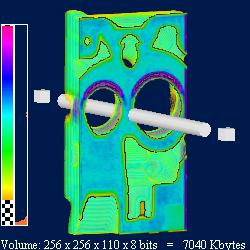
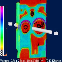
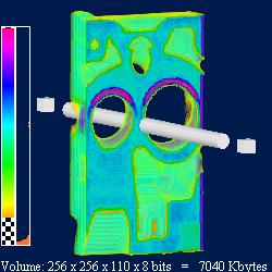
| These figures show an ortho slice clipping a data volume.
Right:
Bottom left:
Bottom right:
| 
|
| 
|
Slice number.
The documentation for this class was generated from the following file:
- VolumeViz/nodes/SoOrthoSlice.h