SoVolumeRender Class Reference
[Nodes]
 Renders a data volume using direct volume rendering
More...
Renders a data volume using direct volume rendering
More...
#include <VolumeViz/nodes/SoVolumeRender.h>
 Inheritance diagram for SoVolumeRender:
Detailed Description
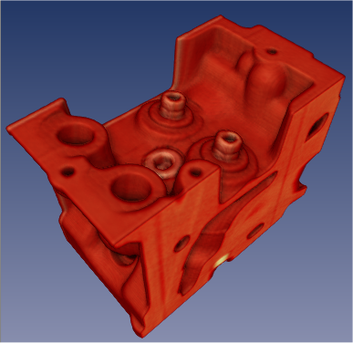
Renders a data volume using direct volume rendering
This node renders volume data using "direct volume rendering". The volume process involves sampling, interpolation, classification and composition. By default the rendering algorithm is a GPU-based technique called raycasting. Raycasting has similarities to the well known algorithm called raytracing, but is specialized for volume data (renders voxels not triangles) and does not currently implement reflection or refraction. One or more "rays" are cast through the volume from each relevant pixel on the screen. Samples are taken at intervals along each ray. The sample interval is controlled by the numSlices and numSlicesControl fields At each sample point a value is interpolated from the closest voxels. The interpolation technique is controlled by the interpolation field. Classification means that color and opacity are computed based on the current SoDataRange and SoTransferFunction (and possibly values from other volumes - see SoVolumeShader). Optional rendering effects may modify the base color and/or opacity. These effects are controlled by an SoVolumeRenderingQuality node and include lighting, shadows, edge coloring, boundary opacity and more. The sample is then composited with other samples along the ray. Composition is controlled by the renderMode field. By default colors are combined based on the opacity of the sample (alpha blending). The ray is terminated if it reaches full opacity or reaches the current depth in the depth buffer. If raycasting is not enabled (SoVolumeShader::raycasting field), the volume is rendered by drawing "slices" (texture mapped polygons) from the back to the front. This effectively samples the volume. Interpolation and classification are done the same way as raycasting, but composition is done by the graphics hardware, so only alpha blending is available.
For a volume containing scalar data values, each voxel's basic RGBA value is determined by the current SoDataRange and SoTransferFunction nodes. This value is combined with current diffuse color and transparency (set, for example, with an SoMaterial node). This means that, for example, the current transparency can be used as a global alpha scale factor to decrease the opacity of all voxels. By default, scalar values are loaded on the GPU and the GPU interpolates between the data values before applying the color map. See the interpolation field for options. To force RGBA values to be loaded (implies color map is applied on the CPU and GPU interpolates between color values), see the usePalettedTexture field in the SoVolumeData node.
For an RGBA volume, each voxel's base RGBA value comes directly from the volume data (SoDataRange and SoTransferFunction are ignored). However if lighting is enabled, the final voxel color is also affected by the emissiveColor, specularColor and shininess fields of SoMaterial.
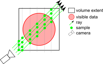
The samplingAlignment field controls whether the samples are axis aligned (perpendicular to one axis of the volume), view aligned (perpendicular to the view direction) or boundary aligned (each ray starts at the first intersected voxel with alpha value > 0). Generally boundary aligned slices should be used (better image quality). Using SoVolumeGroup, SoVolumeIsoSurface or SoProjection nodes will automatically switch to view-aligned samples.
The property nodes SoVolumeIsoSurface and SoVolumeDataDrawStyle add additional rendering styles and can be used, for example, to force SoVolumeRender to draw a GPU computed isosurface instead of volume rendering.
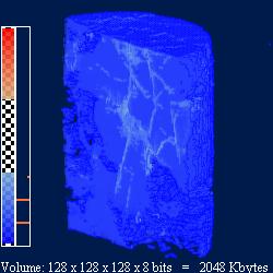
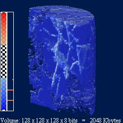
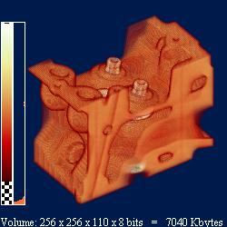
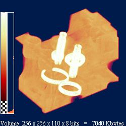
Example rendering:
| lighting = FALSE | lighting = TRUE |
| 
|
| composition = ALPHA_BLENDING | composition = MAX_INTENSITY |
| 
|
Multiple volumes:
VolumeViz provides several mechanisms for combining or rendering multiple volumes, depending on the application's specific requirements. There are several cases:
- CPU data combining
The data values from multiple volumes can be combined on the CPU during data loading, using the SoDataCompositor node. For example computing the "difference" between two volumes on the fly. SoLDMDataTransform and SoVolumeTransform can be used to modify data for a single volume, for example scaling data values or computing a derived data set. SoLDMDataTransform is applied when data is loaded and SoVolumeTransform is applied before data is transferred to the GPU.
- Multiple independent volumes
These are volumes in the same scene that are completely independent (but might overlap in space) or have different dimensions or different extents. For example, medical datasets from different modalities. No special handling is required for rendering slices, including volume skin, or when the color map is opaque. When transparent volumes overlap in space, use the SoVolumeGroup node above the volume data and rendering nodes to ensure that the rendering is properly interleaved.
- Multiple data sets
These are volumes that are really multiple data sets on the same "grid", in other words volumes having exactly the same dimensions and extent. For example, seismic attribute volumes. These volumes can be combined on the GPU using a simple fragment shader function. For example, replacing the VVizComputeFragmentColor (GLSL) function allows "co-blending" the colors from multiple volumes. See SoVolumeShader for more details. Use an SoMultiDataSeparator node to group the volume data nodes that should be combined.
Custom shaders:
The SoVolumeShader node allows a variety of custom shader functions to be defined for special computation or rendering effects on single volumes or multiple volumes. All of these features require programmable shader support on the GPU. Be sure to use an SoMultiDataSeparator (instead of SoSeparator) when combining multiple volumes.
Lighting:
The SoVolumeRenderingQuality property node allows you to to enable GPU computed lighting based on the first SoLight node in the scene graph. (Note that this is typically the viewer's "headlight".) VolumeViz supports two lighting algorithms. They are both computed on the GPU and are independent (but normally only one should be enabled).
- Gradient lighting
Computes the effect of lighting for every sample along the ray, similar to the computation for polygonal geometry, but using a gradient vector computed from the voxel data values instead of a normal vector. Gradient lighting is enabled by the SoVolumeRenderingQuality lighting field. Gradient lighting is the classic solution but can have problems in relatively homogeneous regions where the gradient magnitude is small and gradient direction somewhat random. Multiple fields affect this computation including interpolation, gradientThreshold, gradientQuality and surfaceScalarExponent. - Deferred lighting
Computes the effect of lighting for every visible voxel, as a post-processing step, using a gradient vector computed from the (visible) voxel depth values. Deferred lighting is enabled by the SoVolumeRenderingQuality deferredLighting field. Deferred lighting generally provides better performance because fewer lighting computations are needed. Deferred lighting generally provides better image quality for volumes that inherently contain surfaces (sharp gradients) like medical and industrial scans. Deferred lighting is most effective when the opacity values in the transfer function are approximately binary (mostly 0 and 1 values). See also the opacityThreshold field.
- Warning: CPU computed lighting can be enabled using the lighting field in this node. In this case the lightDirection and lightIntensity fields control the light. Note that when lighting is computed on the CPU, RGBA textures are loaded on the GPU, so color map changes generally require re-loading all the data textures. NOTE: This feature is obsolete. Use SoVolumeRenderingQuality::lighting instead.
-
Gradient lighting Deferred lighting 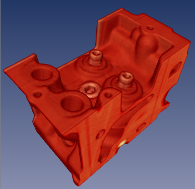
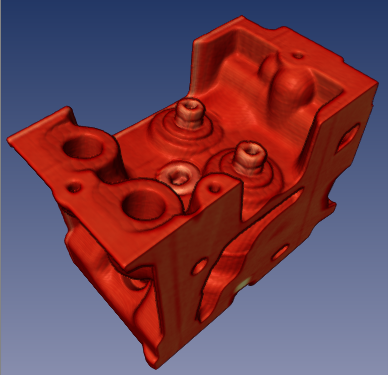
Shadows:
Open Inventor shadow rendering works for volume rendering similar to any other geometry. When shadow rendering is enabled (see SoShadowGroup), non-transparent voxels can cast and receive shadows (see SoShadowStyle). Shadow rendering is independent of whether lighting is enabled for the volume.
SoVolumeRender also supports "ambient occlusion" rendering (see ambientOcclusion field in SoVolumeRenderingQuality). This rendering mode is visually a kind of self-shadowing and represents an approximation of the effect of ambient global lighting in the scene. Ambient occlusion can be combined with gradient or deferred lighting and with shadow casting.
-
Shadow casting Ambient occlusion 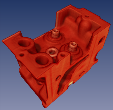
Clipping:
VolumeViz provides multiple tools for clipping volume rendering. Any or all of these tools may be combined for more complex clipping situations. Note that these tools clip all volume shapes including slices.
- The SoROI (Region of Interest) node limits volume rendering to a subvolume. The SoROI node's EXCLUSION_BOX mode can also be used to exclude a sub-region, forming what is sometimes called a "chair cut". Note that the Region of Interest also limits data loading , so it is valuable when the total size of the volume exceeds the available system memory.
- The SoVolumeClippingGroup node clips volume rendering to any closed shape defined by a group of standard Open Inventor geometry nodes. Both "inside" and "outside" clipping are supported. The SoScreenDrawer, SbExtrusionGenerator and SoCSGShape nodes are useful for creating clipping geometry for interactive volume "sculpting".
- The SoUniformGridClipping and SoUniformGridProjectionClipping nodes clip volume rendering against one or more surfaces defined by a height field. This is particularly useful in seismic applications for clipping against (or between) horizon surfaces.
- The SoVolumeMask node can be used to clip volume rendering against a boolean mask volume on a per-voxel basis. But the mask mechanism is much more powerful than that. Each region can have its own transfer function (color map) using SoTransferFunction nodes. Each region can also have its own draw style (volume rendering, isosurface or boundary) using SoVolumeDataDrawStyle nodes. Each region, including the original unmasked volume, is only visible if there exists a transfer function (SoTransferFunction) with the same id value.
Picking:
SoRayPickAction handles picking of VolumeViz shapes similar to other geometry in the scene, but with additional features. Picking on an SoVolumeRender node can return the first non-transparent voxel "hit" or the entire set of intersected voxels along the pick ray. Similar to other geometry, SoPickedPoint can return a "detail" class specific to SoVolumeRender. SoVolumeRenderDetail returns the IJK (voxel coordinate) position of the pick and the data value at that point.
Since Open Inventor 8.6, the SoVolumeRender node (by default) uses the GPU to compute the picked voxel during an SoRayPickAction. For this to work, the SoRayPickAction must have its scene manager initialised using the method SoAction::setSceneManager(). SoHandleEventAction does this automatically, so it is not necessary for the application to take any action when using (for example) an SoEventCallback node and calling the getPickedPoint() method. However if the application creates its own SoRayPickAction then it should set the scene manager. If no scene manager is specified, a warning message is issued and software picking is done. If necessary, using the GPU for volume picking may be disabled by setting the environment variable IVVR_GPU_PICKING to 0 (see SoPreferences).
Projection:
The SoVolumeRender node supports projected volume rendering, for example rendering a volume defined on a grid of latitude / longitude coordinates. Projection is enabled by adding an SoProjection node before the SoVolumeRender node (see SoProjection for more information about supported coordinate systems, ellipsoids and map projections). The projection quality versus speed ratio can be controlled using the new projectedTileSubdivision field that defines how often each tile's geometry will be subdivided when projected. This is important because only the corner points of the tiles are projected, not the individual voxels. So subdividing the tiles provides a better approximation of the actual shape of the grid. Volume projection works with both regular (uniform voxel spacing) and rectilinear (non-uniform voxel spacing) grids. SoProjection automatically selects view-aligned sampling.
Warning:
- Volume projection is incompatible with some rendering options enabled by this node.
The useEarlyZ and gpuVertexGen fields are ignored. - Volume projection is incompatible with some options enabled by the VolumeRenderingQuality node.
Do not enable the preIntegrated, jittering or edgeDetect2D fields. - Volume projection requires all culling to be disabled.
The following options in class SoLDMGlobalResourceParameters should be disabled: setScreenResolutionCulling (default is false), setViewpointRefinement (default is TRUE) and setViewCulling (default is TRUE).
Performance:
Volume rendering performance is affected by many factors including the size of the volume and the rendering options selected. Image quality is also affected by many rendering options and, in general, higher quality implies lower performance. Some of the factors affecting volume rendering performance are:
- Number of voxels:
This mainly depends on the size of the volume, but can be reduced using an SoROI (region of interest) node.
- Number of pixels:
A larger number of pixels means a larger number of rays must be cast through the volume and therefore the shader execution time on the GPU will be longer. This effect is most noticeable when high quality rendering options are enabled. The number of pixels rendered can be temporarily reduced by setting the lowResMode field to DECREASE_SCREEN_RESOLUTION. This reduces the number of times the shader programs running on the GPU must be executed.
- Number of samples (slices):
This is controlled by the numSlices and numSlicesControl fields. Note that better image quality can obtained with the same number of samples by enabling options like preintegrated rendering (see SoVolumeRenderingQuality) and/or the BOUNDARY_ALIGNED setting for samplingAlignment. The number of samples can be automatically decreased when interacting using an SoInteractiveComplexity node.
Since Open Inventor 9.2, we recommend to set the numSlicesControl field to AUTOMATIC and the numSlices field to -1. The number of samples will be computed based on the dimensions of the volume (number of voxels on each axis), the SoComplexity::value setting and the viewing direction. If the viewing direction changes, the number of samples will be automatically adjusted.
- Opacity:
Increasing the number of opaque, or nearly opaque, voxels in the volume (using SoTransferFunction) will generally improve performance because the sampling rays can terminate sooner. See also IVVR_ALPHA_THRESHOLD_INTERACTIVE in SoPreferences.
If you are using a completely opaque transfer function, for example with a "volume probe", SoVolumeSkin will generate the same image much faster.
- Rendering options:
Many of the advanced rendering options and rendering effects enabled by SoVolumeRenderingQuality have an additional performance cost. These include lighting, edge coloring, boundary opacity, cubic interpolation and gradient quality. These settings can be automatically changed while interacting using an SoInteractiveComplexity node.
- Tile size:
For backward compatibility, the default tile size is still only 64. This is quite small for modern CPU/GPU hardware. The smaller the tile size, the larger the total number of tiles that must be managed by VolumeViz. This overhead can be significant, especially for operations that require reloading the data textures on the GPU, for example, changing the data range (SoDataRange). For smaller volumes, like 512^3, it can be efficient to set the tile size large enough to contain the entire volume. For very large volumes, larger tile sizes are efficient for SoVolumeRender but somewhat inefficient for slice rendering because complete tiles must be loaded even though the slice only uses part of the data (see also SoSlice::largeSliceSupport). Applications should experiment.
For volumes stored in LDM file format, the tile size must be specified when the volume is converted to LDM (see SoConverter and the "-t" option). For other data data formats the tile size can be specified using the SoVolumeData node's ldmResourceParameters field, but only after setting the filename field or calling the setReader() method.
- LDM_USE_IN_MEM_COMPRESSION
This environment variable (see SoPreferences) affects much more than its name implies. VolumeViz always manages data as "tiles", regardless of the data format. In many cases VolumeViz must create (or uncompress) the tiles at run time. These cases include in-memory volumes, any volume reader that does not implement the readTile() method (all built-in formats except LDM) and compressed LDM format files. If this variable is true ( the default value), then VolumeViz only keeps a small cache of tiles in memory. See the SoBufferObject method getBufferObjectCache() for the current default and note that this setting is separate from the max main memory parameter. If a tile's data is needed and that tile is not in the cache, the tile must be recreated. This overhead can be significant, especially for operations that require recreating data textures on the GPU, for example, changing the data range (SoDataRange). We recommend setting this variable to false unless the memory conserving feature for compressed tiles is critical.
VolumeViz keeps tiles from a compressed LDM format file in CPU memory as compressed data. This option allows more tiles to be kept in the same amount of CPU memory, but incurs a performance penalty because a tile must be uncompressed when its data is needed, unless it is found in a small cache of uncompressed tiles (see SoBufferObject::getBufferObjectCache). This penalty is particularly noticeable for operations that require recreating data textures on the GPU, for example changing the data range (SoDataRange).
If rendering performance is too slow, it may be necessary to render with high quality settings when the user is not interacting with the scene, but temporarily switch to high performance (lower quality) settings when the user is interacting. Open Inventor automatically sets "interactive mode" when the user is moving the camera or moving a dragger. The application can explicitly set interactive mode, for example while the user is moving a slider in the user interface. Some important tools are:
- LowResMode
For example, set the lowResMode field to DECREASE_SCREEN_RESOLUTION and set the lowScreenResolutionScale field to 2 or 4. In interactive mode VolumeViz will render the volume at lower resolution (reducing the number of sample rays and shader executions).
- SoInteractiveComplexity
This node allows you to specify different values to use for certain fields in interactive mode. For example set a smaller value for SoComplexity::value (reduces the number of samples) or turn off an expensive rendering option. The values specified in SoInteractiveComplexity override the actual fields in the scene graph.
Limitations:
- Multi-thread rendering:
Unlike most Open Inventor nodes, VolumeViz nodes do not support simultaneous rendering in multiple threads (even when Open Inventor is initialized using one of the initThread() methods).
- Geometric transforms:
The volume size (extent in 3D space) and orientation can be modified by transformation nodes in the scene graph just like any geometry. For a volume this in turn modifies the appearance of volume rendering nodes like SoVolumeRender. However please note: The same transformation must be applied to the volume data node and all volume rendering nodes associated with that volume. So effectively any transformation nodes that affect the volume must be placed before the volume data node.
EXAMPLE
- For simple data sets, a basic VolumeViz rendering could be achieved with only a few nodes: minimally an SoVolumeData node to identify the data set and one rendering node. However most data sets need at least some of the additional nodes shown here in order to get a correct and useful rendering. Most applications will need additional nodes to take advantage of region of interest, interaction, clipping and other VolumeViz features. Please consider the code shown here as simply a guideline and a starting point for exploring the many powerful features available in Open Inventor.
Note that some of the property nodes (data, material, color map, etc) will typically be shared by multiple rendering nodes. For example the volume data usually only needs to be loaded once, using a single SoVolumeData node. Multiple slices and/or regions can be rendered using that data node and they may use the same transfer function or each have their own.
Also note that this example is for a data volume, not a label volume. Please see the notes about label volumes following the code block.
// Default setting can be a performance bottleneck SoPreferences::setValue( "LDM_USE_IN_MEM_COMPRESSION", "0" ); // Keep volume viz separate from geometry SoSeparator* volSep = new SoSeparator(); root->addChild( volSep ); // Decrease the quality while moving to have better interactivity SoInteractiveComplexity* interact = new SoInteractiveComplexity(); // Decrease the number of samples interact->fieldSettings.set1Value( 0, "SoComplexity value 0.2 0.5" ); // Decrease interpolation quality. interact->fieldSettings.set1Value( 1, "SoVolumeRender interpolation LINEAR CUBIC" ); // Dont wait before returning to full quality rendering. interact->refinementDelay = 0; volSep->addChild( interact ); // Complexity node for the interact node to control. SoComplexity* volComp = new SoComplexity(); volSep->addChild( volComp ); // Load volume data SoVolumeData* volData = new SoVolumeData(); volData->fileName = "$OIVHOME/examples/source/VolumeViz/Data/3DHead.vol"; volSep->addChild( volData ); // Set range of data values to visualize. // Not required for 8-bit voxels, critical for larger data types. // The getMinMax() call may be expensive for non-LDM file formats. SoDataRange* volRange = new SoDataRange(); if (volData->getDatumSize() > 1) { double minVal, maxVal; volData->getMinMax( minVal, maxVal ); volRange->min = minVal; volRange->max = maxVal; } volSep->addChild( volRange ); // Load constant intensity with alpha ramp SoTransferFunction* volTF = new SoTransferFunction(); volTF->predefColorMap = SoTransferFunction::GRAY; volTF->minValue = 10; // Make "noise" voxels transparent volSep->addChild( volTF ); // Display volume at full intensity SoMaterial* volMat = new SoMaterial(); volMat->diffuseColor.setValue( 1, 1, 1 ); volSep->addChild( volMat ); // Volume rendering settings SoVolumeRenderingQuality* volQual = new SoVolumeRenderingQuality(); // Remove tile boundary artifacts while moving. volQual->interpolateOnMove = TRUE; // Higher quality rendering volQual->preIntegrated = TRUE; // Optional: Enable screen space lighting volQual->deferredLighting = TRUE; // Optional: If using gradient lighting, increase quality volQual->lightingModel = SoVolumeRenderingQuality::OPENGL; volQual->surfaceScalarExponent = 5; volSep->addChild( volQual ); // Display volume rendering SoVolumeRender* volRend = new SoVolumeRender(); // Let Inventor compute best number of slices volRend->numSlicesControl = SoVolumeRender::AUTOMATIC; // Optional: Use lower screen resolution while moving. volRend->lowResMode = SoVolumeRender::DECREASE_SCREEN_RESOLUTION; volRend->lowScreenResolutionScale = 2; // Remove "slicing" artifacts volRend->samplingAlignment = SoVolumeRender::BOUNDARY_ALIGNED; // Ignore low visibility voxels (OIV 9.3) volRend->opacityThreshold = 0.1f; volSep->addChild( volRend );
- A label volume, also known as a label field, is usually the result of doing some sort of segmentation on a data volume. Each voxel value is an integer label (id) identifying which material, object, etc that the voxel belongs to. There could be 100s or 1000s of labels, but there might be as few as 8 label values. For example, a simple label volume might have 7 opaque materials plus plus an exterior material which is completely transparent. Conceptually, there is one big difference between a (typical) data volume and a label volume. A data volume is conceptually a set of discrete samples taken from a continuous scalar field. So we know the exact value at the center of each voxel and interpolate between those values to get the value at any position in between voxels. In a label volume we normally consider each voxel to belong completely to one material, so the value is constant until we cross the boundary into the next voxel. Therefore we do not want to interpolate the label values.
- When rendering a label volume, make the following changes to the above example:
- Set the SoVolumeRender interpolation field to NEAREST and
- Leave the SoVolumeRenderingQuality preintegrated field set to FALSE.
- If rendering isosurfaces (SoVolumeIsosurface), set the SoVolumeRenderingQuality segmentedInterpolation field to TRUE.
- It is also important to set the data range, texture precision and color map size carefully. Please see the label volume discussion in SoTransferFunction.
FILE FORMAT/DEFAULT
- VolumeRender {
| fixedNumSlicesInRoi | FALSE |
| gpuVertexGen | FALSE |
| interpolation | LINEAR |
| lighting | FALSE |
| lightDirection | -1, -1, -1 |
| lightIntensity | 1 |
| lowResMode | DECREASE_NONE |
| lowScreenResolutionScale | 1 |
| numEarlyZPasses | 30 |
| numSlices | -1 |
| numSlicesControl | ALL |
| opacityCorrection | TRUE |
| projectedTileSubdivision | 1 |
| renderMode | VOLUME_RENDERING |
| samplingAlignment | VIEW_ALIGNED |
| subdivideTile | FALSE |
| useEarlyZ | FALSE |
ACTION BEHAVIOR
- SoGLRenderAction
Draws a volume-rendered image based on current SoVolumeData.
SoGetBoundingBoxAction
Computes the bounding box that encloses the volume.
SoRayPickAction
Since Open Inventor version 8.5, picking always returns the first non-transparent voxel intersected by the pick ray. The old behavior can be restored by using an SoPickStyle node set to BOUNDING_BOX.
SEE ALSO
SoVolumeData, SoTransferFunction, SoROI, SoVolumeShader, SoVolumeIsosurface, SoVolumeRenderingQuality, SoProjection, SoVolumeRendering, SoUniformGridClipping, SoVolumeClippingGroup, SoInteractiveComplexity
- See related examples:
-
DenoisingImage3D, MedicalDentalCurveUnfolding, MedicalDicomReader, MedicalMPRViewer, MedicalGLVolumeRender, MedicalMultiChannel, MedicalVolumeTextureCompose, MedicalAmbientOcclusion, MedicalDeferredLighting, Medical4DVolumeRendering, MedicalAnatomicalViews, MedicalDTIViewer, MedicalVolumeDataDrawStyle, MedicalFreeHandCutting, MedicalMarchingCubesSurface, MedicalSegmentation, MedicalSimpleVolumeMask, MedicalVolumeExtract, MedicalVolumePipeClipping, MedicalBonesMuscles, MedicalSimpleVolumeAxis, MedicalVolumePickingGpu, MedicalColorMap, MedicalMultiTransferFunctions, MedicalMPRViewerService, BonesMuscles, LDMMandelBulb, VViz-template-SG, AmbientOcclusion, ColorMap, CSGClippingGroup, DataAccessCustomReader, DataTransform, DeferredLighting, GL_VolumeRender, HorizonClipping, MultiChannel_ex1, MultiChannel_ex2, SimpleInteractiveParameters, SimpleShader, SimpleVolume, SimpleVolumeAxis, VolumeExtract, VolumePickingGpu, VolumePipeClipping, VolumeTransform, VolRend
Member Typedef Documentation
| typedef AbortCode SoVolumeRender::SoVolumeRenderAbortCB(int totalElems, int thisElem, void *userData) |
Member Enumeration Documentation
Abort code for callback.
- Enumerator:
CONTINUE Continue rendering as usual.
ABORT The render action of the SoVolumeRender node is aborted.
The render action continues for the remaining part of the scene graph.
SKIP The current slice is not drawn.
Rendering continues with the next slice.
Method to use when moving in low resolution.
Used with lowResMode field.
- Enumerator:
DECREASE_NONE No low resolution mode when moving.
DECREASE_SLICES Decrease the number of samples according to SoComplexity::value when moving.
It has no effect if numSlicesControl is set to AUTOMATIC because this mode always uses the SoComplexity node to compute the number of samples to draw.
DECREASE_SCREEN_RESOLUTION Downscale the screen resolution of the volume when moving by the factor defined in lowScreenResolutionScale.
Number of samples control mode.
Used with numSlicesControl field.
- Enumerator:
ALL Use all samples
The number of samples depends on the viewing direction.MANUAL Use the number of samples specified by the numSlices field.
The number of samples does not depend on the viewing direction.
AUTOMATIC (Recommended) Use a number of samples computed as follows:
If numSlices is greater than zero, then
n = complexity * 2 * numSlices
where complexity comes from the value field of the SoComplexity node and numSlices comes from the numSlices field.The number of samples does not depend on the viewing direction.
If numSlices is any value less than or equal to 0, the dimension of the volume data is used instead of numSlices, so
n = complexity * 2 * volumeDimension
The number of samples depends on the viewing direction.The factor 2 is used because by default complexity is equal to 0.5. So, by default, the behavior for numSlices greater than zero is the same as MANUAL and the default behavior for numSlices less than or equal to zero is the same as ALL.
You can increase the complexity up to 1.0, which would double the number of samples used. You can decrease the complexity to reduce the number of samples used. The global alpha is corrected so that the brightness looks the same.MAIN_AXIS Use a number of samples computed as follows:
n = complexity * 2 * volumeDataDimension[mainVisibleAxis]
where complexity comes from the value field of the SoComplexity node.The number of samples depends on the viewing direction.
NOTE: enumeration value available since Open Inventor 8.1
Composition mode.
See the renderMode field. NOTE: enumeration value available since Open Inventor 9.1
- Enumerator:
VOLUME_RENDERING Alpha compositing (Default).
MIN_INTENSITY_PROJECTION Minimum intensity projection (MinIP).
The minimum value found along each ray is used to determine color.
MAX_INTENSITY_PROJECTION Maximum intensity projection (MIP).
The maximum value found along each ray is used to determine color.
SUM_INTENSITY_PROJECTION Ray sum intensity projection (RSP).
The values found along each ray are accumulated. Then the total value is normalized by the nominal number of samples for every ray (see numSlices), which is the same for all rays. The values seen in shader functions, e.g. VVizComputeFragmentColor are still in the range 0..1, but the range of values that represents is quite different from the voxel data range.AVERAGE_INTENSITY_PROJECTION Average Intensity projection (AIP).
The values found along each ray are accumulated. The total value is divided by the actual number of samples along the current ray. The actual number of samples may be different for each ray. The resulting data range will be similar to the voxel data range but not necessarily the same. If there are many low, e.g. 0, valued voxels, the average may be very small.
Sampling alignment.
Used with the samplingAlignment field. NOTE: enumeration value available since Open Inventor 9.1
- Enumerator:
VIEW_ALIGNED Samples are located on planes perpendicular to the view direction.
DATA_ALIGNED Samples are located on planes perpendicular to one axis of the volume.
BOUNDARY_ALIGNED Samples are located on shells aligned with the volume's internal "boundary".
Each ray begins sampling at the first intersected voxel that has an alpha value > opacityThreshold.
SMOOTH_BOUNDARY_ALIGNED Similar to BOUNDARY_ALIGNED but uses a cubic interpolation to compute the boundary, giving smoother results when using SoVolumeRenderingQuality::deferredLighting.
When using linear interpolation and deferred lighting, BOUNDARY_ALIGNED can generate "flat shading" due to linear interpolation between voxels. SMOOTH_BOUNDARY_ALIGNED will generate a smooth shading using a cubic interpolation to find the volume's boundary and use a linear interpolation for the rest of volume. This is a good compromise between result and performances of a full tricubic interpolation. Please refer to SoVolumeRenderingQuality::deferredLighting and SoVolumeShape::interpolation for details. LIMITATIONS SMOOTH_BOUNDARY_ALIGNED is not supported in the following case:
- With isosurface rendering
- When using gradients computed from the voxel values (SoVolumeRenderingQuality::lighting for instance).
- When using SoUniformGridClipping nodes. In one of the above case, BOUNDARY_ALIGNED is used.
- Warning:
- Possibly heavy GPU usage
Constructor & Destructor Documentation
| SoVolumeRender::SoVolumeRender | ( | ) |
Constructor.
Member Function Documentation
| static SoType SoVolumeRender::getClassTypeId | ( | ) | [static] |
Returns the type identifier for this class.
Reimplemented from SoVolumeShape.
| virtual SoType SoVolumeRender::getTypeId | ( | ) | const [virtual] |
Returns the type identifier for this specific instance.
Reimplemented from SoVolumeShape.
| void SoVolumeRender::setAbortCallback | ( | SoVolumeRenderAbortCB * | func, | |
| void * | userData = NULL | |||
| ) |
Sets callback to call during texture map rendering to test for an abort condition.
When not in raycasting mode, it will be called for each element that is rendered.
In the case of LDM, an element is a tile, totalElems is the number of tiles that will be drawn, and thisElem is the number (counting from one) of the next tile to be drawn. The quotient thisElem / totalElems represents the progress of the volume rendering process.
In the non-LDM case, an element is a slice, totalElems is the number of slices that will be drawn, and thisElem is the number (counting from one) of the next slice to be drawn. The quotient thisElem / totalElems represents the progress of the volume rendering process.
This allows applications to terminate rendering of this node prematurely if some condition occurs. It does not terminate traversal of the scene graph. (For that use the SoGLRenderAction abort callback.) The callback function should return one of the AbortCode codes to indicate whether rendering should continue.
| void SoVolumeRender::setRenderProgress | ( | SoProgressIndicator * | ps | ) | [inline] |
Set an application defined SoProgressIndicator object which will raise an event before and after the volume rendering task, before and after each subtask (in this case: Texture creation and Geometry creation) and after each step in the subtasks which represents in most cases individual tiles of data.
This method is useful to track loading time of the first frame if in fixedResolution mode.
- onBeginTask / onEndTask will be raised only one time per frame : "Rendering".
- onBeginSubTask / onEndSubTask will be raised 2 times per frame : "Loading Texture" and "Create Geometry".
- onEndStep will be raised "number of tiles" times per subtask.
If set to NULL no events will be raised. Default is NULL.
Since Open Inventor 9.9Friends And Related Function Documentation
friend class SoVolumeRenderInterface [friend] |
friend class SoVolumeRenderLdm [friend] |
friend class SoVolumeRenderRaycast [friend] |
Member Data Documentation
When this field is set to FALSE (the default), the number of samples set by numSlices is the number of samples used for the region defined by the current ROI.
Therefore the number of samples may change when the ROI size changes. When TRUE, numSlices is the number of samples for the whole volume. In this case the sample density is constant, independent of the ROI size. Default is FALSE.
NOTE: field available since Open Inventor 7.1
| SoDEPRECATED SoSFBool SoVolumeRender::gpuVertexGen |
If TRUE, slice vertices used for volume rendering are generated by the GPU instead of the CPU.
This can increase performance when a large number of samples is being used. Default is FALSE.
NOTE: This field is ignored in raycasting mode or when doing volume projection (SoProjection or subclasses are in effect).
NOTE: field available since Open Inventor 7.0
- Deprecated:
-
Deprecated since Open Inventor 9630
No longer used. Only raycasting mode is supported.
| SoDEPRECATED SoSFVec3f SoVolumeRender::lightDirection |
Light direction (relative to the volume).
The default is (-1,-1,-1). Only affects CPU computed lighting (i.e. when the lighting field is TRUE).
- Deprecated:
-
Deprecated since Open Inventor 8500
Use SoVolumeRenderingQuality::lighting field instead.
| SoDEPRECATED SoSFBool SoVolumeRender::lighting |
Indicates if lighting is required.
Default is FALSE.
NOTE: Better performance for lighting can be obtained using the SoVolumeRenderingQuality node. Using SoVolumeRenderingQuality, lighting is determined by the first light in the scene graph (similar to other geometry) and the lighting computation is done on the GPU (therefore SoVolumeRenderingQuality requires programmable shaders).
Using the lighting field, lighting is determined by the lightDirection field and the lighting computation is done on the CPU. This requires RGBA textures to be loaded on the GPU which uses more texture memory and requires more time to modify the transfer function (color map) because textures must be reloaded. Note that activating or deactivating lighting will also normally force the textures to be recreated, which may be slow.
NOTE: Only set the lighting field to TRUE in SoVolumeRenderingQuality or SoVolumeRender. Do not set both lighting fields to TRUE.
- Deprecated:
-
Deprecated since Open Inventor 8500
Use SoVolumeRenderingQuality::lighting field instead.
| SoDEPRECATED SoSFFloat SoVolumeRender::lightIntensity |
Light intensity in the range [0-1].
The default is 1. Only affects CPU computed lighting (i.e. when the lighting field is TRUE).
- Deprecated:
-
Deprecated since Open Inventor 8500
Use SoVolumeRenderingQuality::lighting field instead.
Sets the method to use when moving in low resolution.
Use enum LowResMode. Default is DECREASE_NONE.
- DECREASE_NONE: Default. Do not use low resolution mode when moving (i.e., when the viewer is moving the camera).
- DECREASE_SLICES: Decrease the number of samples according to SoComplexity::value when moving. It has no effect if numSlicesControl is set to AUTOMATIC because in this case, VolumeViz always uses the SoComplexity node to compute the number of samples.
- DECREASE_SCREEN_RESOLUTION: Downscale the screen resolution of the volume when moving by the factor specified in lowScreenResolutionScale. This is the recommended setting when rendering performance is too low.
NOTE: field available since Open Inventor 7.0
If lowResMode is DECREASE_SCREEN_RESOLUTION, render the volume at a lower screen resolution.
when moving. The resolution used is the current screen resolution divided by lowScreenResolutionScale. Default is 1. A value of 2 or 4 is recommended if using this option.
NOTE: field available since Open Inventor 7.0
| SoDEPRECATED SoSFInt32 SoVolumeRender::numEarlyZPasses |
When useEarlyZ is TRUE, pixels are tested for full opacity every N samples, where N is the value of this field.
Default is 30.
NOTE: This field is ignored in raycasting mode (the default).
NOTE: field available since Open Inventor 7.0
- Deprecated:
-
Deprecated since Open Inventor 9630
No longer used. Only raycasting mode is supported.
Specifies the number of samples along each ray.
The default is -1, which means to use the volume dimensions (number of voxels on each axis) when the numSlicesControl field is set to AUTOMATIC.
NOTE: This value is not used if the numSlicesControl field is set to ALL (the default for that field).
Controls how the number of samples along each ray is determined.
Use enum NumSlicesControl. Default is ALL. Generally increasing the number of samples will increase the image quality, but decrease the performance (frames per second).
Since Open Inventor 9.2, we recommend to set the numSlicesControl field to AUTOMATIC and the numSlices field to 0. The number of samples will be computed based on the dimensions of the volume (number of voxels on each axis), the SoComplexity::value setting and the viewing direction. If the viewing direction changes, the number of samples will be automatically adjusted.
Note if raycasting is not used, then this field is the number of "slices", meaning the number of texture mapped polygons that will be drawn to render the volume. Generally the implications of smaller or larger values on image quality and performance are the same.
Controls whether opacity correction is done.
If TRUE, opacity is automatically adjusted to give similar appearance no matter how many samples are used. If FALSE, opacity is not corrected and increasing the number of samples will increase the opacity. Default is TRUE.
Generally this field should always be set to true. NOTE: field available since Open Inventor 8.1
Specifies a threshold opacity (alpha) value that defines voxels considered to be "solid" (non-transparent).
Many volume data sets are composed of objects of interest floating in an approximately transparent "fog", depending on opacity values in the transfer function. Several effects like BOUNDARY_ALIGNED sampling, ambientOcclusion and deferredLighting need to locate the boundary between solid objects and ambient fog. This field defines a threshold in the range [0, 1]. Voxels are considered solid if their alpha value is greater than opacityThreshold.
A value of 0.0 generally works well with a transfer function containing "binary" opacity (a transfer function with only fully transparent or fully opaque colors). If this is not the case, you should set this value according to your visualization parameters. Generally between 0.1 and 0.5.
Default is 0.0, meaning that the boundary is considered to be the first voxel along each ray with alpha > 0.
NOTE: field available since Open Inventor 9.3When doing volume projection (see SoProjection), only the geometry (corner vertices) of the LDM tiles are projected, not the individual voxels.
This can produce an imprecise projected volume when using large LDM tiles or low resolution levels (where the LDM tiles are larger).
This field controls how many times the tile geometry will be subdivided (producing more vertices) before being projected. Subdivision gives a smoother, more accurage shape, but requires much more computational power and may reduce rendering performance. Default is 1 (subdivide once).
NOTE: This field is ignored in raycasting mode (the default).
Specifies the composition mode.
Composition controls how the voxels along each sampling ray are combined to form the final image. Use enum RenderMode. Default is VOLUME_RENDERING (alpha blending).
VOLUME_RENDERING blends the R, G, and B components for each data value along the sampling ray based on the alpha value (alpha blending).
MIN_INTENSITY_PROJECTION draws only the color associated with the minimum data intensity along the sampling ray.
MAX_INTENSITY_PROJECTION draws only the color associated with the maximum data intensity along the sampling ray.
SUM_INTENSITY_PROJECTION draws only the color associated with the sum of all data values along the sampling ray. The values seen in shader functions, e.g. VVizComputeFragmentColor are still in the range 0..1, but the range of values that represents is quite different from the voxel data range.
AVERAGE_INTENSITY_PROJECTION draws only the color associated with the average of all data values along the sampling ray. If there are many low, e.g. 0, valued voxels, the average may be very small. You may be able to use SoROI (Region of Interest) to remove some of these voxels.
Note: When using a renderMode other than VOLUME_RENDERING (alpha blending):
- Only raycasting mode is supported
- No depth information is retained.
- SoVolumeRenderingQuality::preIntegrated cannot be enabled
Specifies which technique to use to align rayCast samples.
Use enum SamplingAlignment. Default is VIEW_ALIGNED.
VIEW_ALIGNED: Samples are located on planes perpendicular to the view direction.
This generates the same result as the sliced view aligned (non-raycasting) rendering mode.
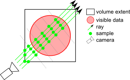
DATA_ALIGNED: Samples are located on planes perpendicular to one axis of the volume.
This generates the same result as the sliced data aligned (non-raycasting) rendering mode.
BOUNDARY_ALIGNED: Samples are located on shells aligned with the volume's internal "boundary". Each ray begins sampling at the first intersected voxel that has an alpha value > opacityThreshold. This technique greatly decreases "slicing" artifacts even with a relatively small number of slices. Only available in raycasting mode. It is strongly recommended to enable this mode when using SoVolumeRenderingQuality::ambientOcclusion.
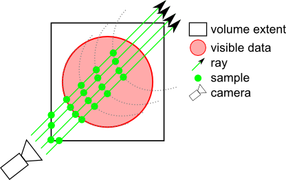
SMOOTH_BOUNDARY_ALIGNED: Similar to BOUNDARY_ALIGNED but uses a cubic interpolation to compute the boundary, giving smoother results when using SoVolumeRenderingQuality::deferredLighting.
NOTE: If an SoVolumeGroup or SoProjection node applies to this node, the field is ignored and VIEW_ALIGNED is used.
NOTE: field available since Open Inventor 9.1If true, LDM tiles will be subdivided for rendering.
Fully transparent sub-tiles won't be rendered, thus (potentially) increasing the speed of the rendering if an expensive shader is being used and significant regions of the volume are fully transparent. However using false is faster if the user will frequently change the data range (e.g. window center/width in medical applications). SubTileDimension can be changed using SoVolumeData node's ldmResourceParameters field. Default is FALSE.
See the 'subtileDimension' field in SoLDMResourceParameters. If the tileDimension is larger than the default value, then the subtileDimension should also be larger to avoid performance issues.
| SoDEPRECATED SoSFBool SoVolumeRender::useEarlyZ |
If TRUE, stop computing when the pixel's cumulative opacity reaches 1.
This can increase performance when an expensive shader is being used. Default is FALSE.
NOTES:
- This field is ignored in raycasting mode (the default) as it is implicitly managed. See IVVR_ALPHA_THRESHOLD_STILL/INTERACTIVE.
- When doing volume projection (SoProjection or subclasses) or composition other than ALPHA_BLENDING, this field is ignored.
NOTE: field available since Open Inventor 7.0
- Deprecated:
-
Deprecated since Open Inventor 9630
No longer used. Only raycasting mode is supported.
| SoDEPRECATED SoSFBool SoVolumeRender::viewAlignedSlices |
Indicates if samples should be computed in a view-aligned manner.
Default is TRUE.
NOTE: If an SoVolumeIsosurface, SoVolumeRenderingQuality or SoProjection node applies to this node, this field is ignored and view-aligned samples are used.
- Deprecated:
-
Deprecated since Open Inventor 9100
Use samplingAlignment field instead.
The documentation for this class was generated from the following file:
- VolumeViz/nodes/SoVolumeRender.h